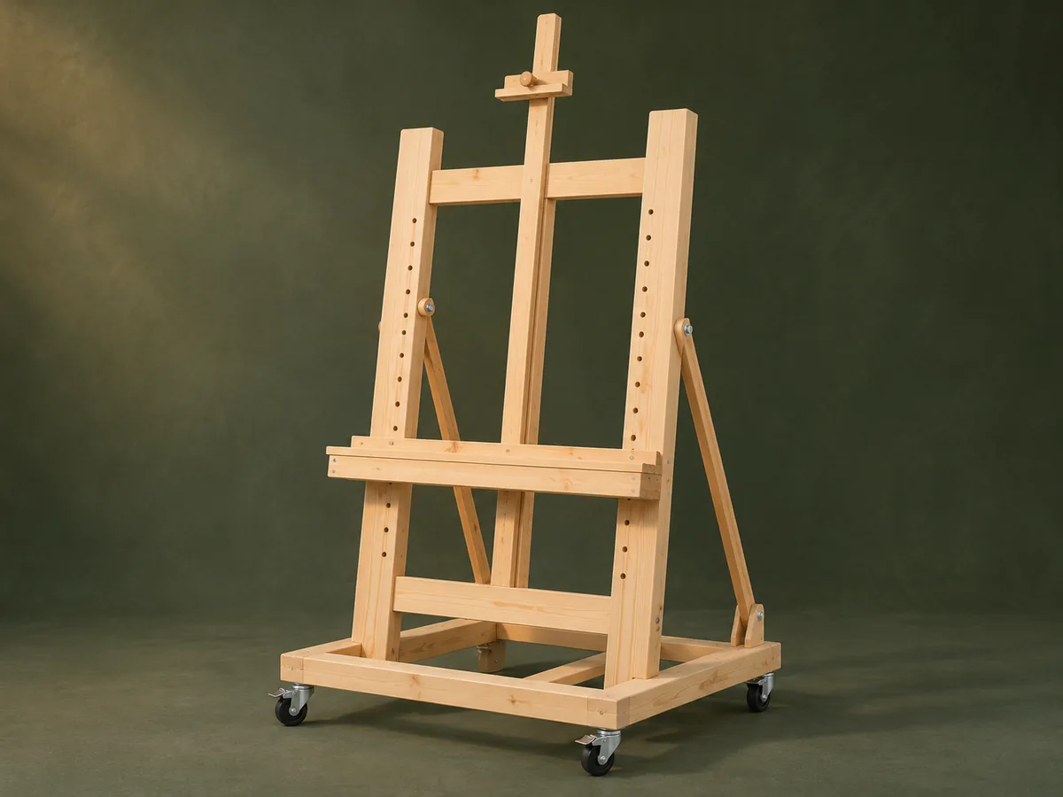
Two rear slotted struts set the tilt.
Project library / Workshop
Workshop / Build companion
Adjustable Studio Easel
A tall H-frame easel has a pegged canvas shelf, sliding top clamp and hinged rear tilt supports.
Intermediate6 stages13-page source
A companion to the original plan. Original guide to the historical easel; not shop-tested. The reported clamp failure and rough shelf adjustment require a tested improvement before supporting valuable artwork.
Understand the project
What makes this build.
Matching sliding shelf carriers, two slotted tilt struts and a reliable top clamp makes this adjustable easel more involved than a fixed frame.
A pegged shelf slides on paired U-shaped carriers.
The center mast supports a separate sliding top clamp.
Points to resolve before building
- The source admits a weak shelf adjustment and a broken one-piece top clamp; resolve and test these details.
- Canvas height is not a rated load capacity; tall or tilted work can overturn the easel.
Prepare the workbench
Materials & tools.
Check what you have, then confirm stock sizes and hardware against your chosen dimensions.
Materials checklist
Tools & operations
- Crosscut saw
- Drill with doweling guide
- Jigsaw or guided router
- Chisels
- Clamps
- Square
Tool choices may include practical editorial suggestions. Use workholding and guarding appropriate to the actual machine and operation.
Choose dry, sound stock and test unfamiliar joints in scrap. Keep guards, push aids, eye protection, and dust control appropriate to the work.
Keep the numbers close
Measurements to know.
Selected dimensions verified from the source. This is not an automatically scaled cutting list.
| Center mast | 7 ft 6 in | Source p. 4 |
|---|---|---|
| Shelf length | 4 ft | Source p. 9 |
| Shelf peg spacing | 2 in | Source p. 10 |
| Rear adjustment slot | 15 in long × ⅜ in wide | Source p. 8 |
Printed diagrams and concept images are not scale references. Verify measurements, material thickness, hardware fit, and allowances before cutting.
Inches to millimeters
Convert a measurement without changing the design. Enter a decimal or a fraction, such as 1 3/8.
Nominal lumber names and actual finished sizes are different. Converting units does not choose a substitute stock size.
From stock to finished project
Let’s make it.
Read the complete sequence before cutting. Mark a stage complete after its fit checks and any required glue cure.
Build the H frame
- Fit the two outer uprights and crossbraces so the shelf can slide on the front faces. Recess the center mast flush at the lower brace and use the narrow spacers described behind it. Check the mast against the horizontal brace spacers while the parts are still accessible, since the top clamp must pass these intersections.
Before moving onA test sleeve travels without hitting the braces.
Assemble the wheeled base
- Notch the side members for the flat front and rear rails, then drill the paired pivot holes. Dry-fit the main frame between the base sides with washer clearance. Keep the pivot holes level across the base and avoid overtightening the nuts until the intended pivot action has been checked.
Before moving onThe main frame pivots freely without side play that distorts the base.
Make the tilt supports
- Prepare the paired hinged rear struts and cut straight adjustment slots in the longer members. Test the bolts through the full slot travel before fitting hinges. Use a spare bolt to test the entire slot, smoothing any narrow section that would make the tilt adjustment jump.
Before moving onBoth struts move through matching ranges without binding.
Fit the adjustable shelf
- Build U-shaped carriers directly to the actual upright thickness. Fit and center the shelf, then drill matching ½-inch peg holes at 2-inch intervals in the uprights. Fit the carriers while on the frame before permanently screwing on the shelf; afterward they cannot simply slide in from the front.
Before moving onBoth shelf pegs engage fully at the same height.
Resolve the top clamp
- Fit a sliding top clamp to the center mast and its spacers. The author reports the heavily hollowed one-piece clamp broke, so develop and test the suggested built-up alternative before trusting a canvas to it. Preserve enough wood around the captured nut and pressure point, and compare the built-up alternative against the reported fracture location.
Before moving onThe clamp holds without cracks or excessive pressure.
Assemble and check adjustment
- Fit the pivots with washers and locking nuts, add the rear struts and install accessible locking casters. Check stability at intended shelf heights and tilt settings with a modest representative load. Adjust the empty easel first and keep hands away from the closing strut joints while tightening both wing nuts.
Before moving onWheel locks, shelf pegs and both tilt locks remain engaged during adjustment.
1 / 6
Progress and notes stay in this browser. Nothing is uploaded.
Source notes.
- Original PDF
- Artists Easel.pdf
- Source length
- 13 pages
- Attribution
- Collection copyright 2004 Martian Auctions; original authorship unverified.
- This edition
- 116 Studio · Original written companion and AI concept image · November 2026
Page references count from the first page of this PDF. The original is retained in the owner’s private woodworking collection; it is not distributed by this website. Consult it for full drawings, templates, and details beyond this companion.
Historical plans can omit essential context. Source references identify where a detail came from; they do not certify the design or replace current manufacturer instructions or applicable professional review.
More from this corner of the shop.
Workshop
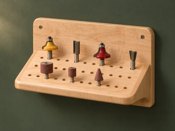
Angled Router-Bit Shelf
A sloping drilled shelf presents router bits and other shanked accessories against a wall backboard.
Beginner5 stages
Workshop
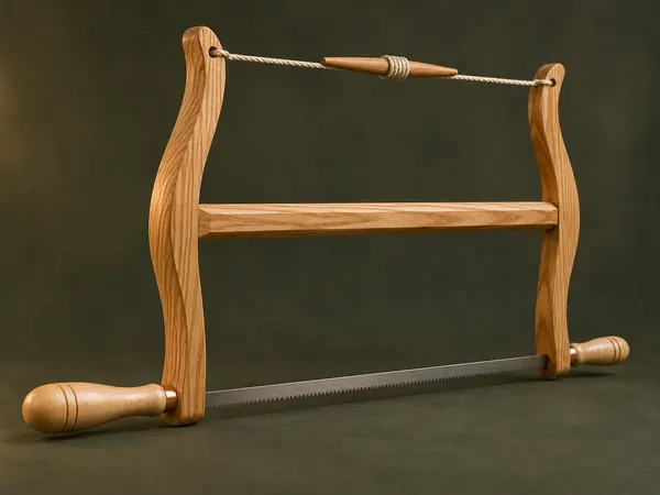
Classic Wooden Bow Saw
An ash H-frame tensions a narrow saw blade with twisted cord and turned maple handles.
Advanced5 stages
Workshop
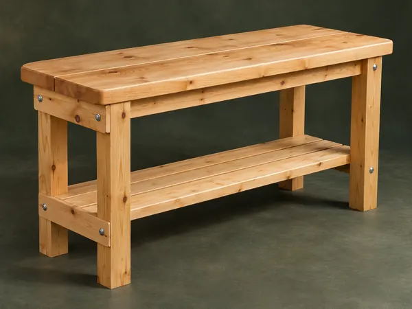
Bolted Plank Workbench
A heavy two-plank worktop rests on housed bolted end frames with a narrow slatted shelf below.
Intermediate5 stages