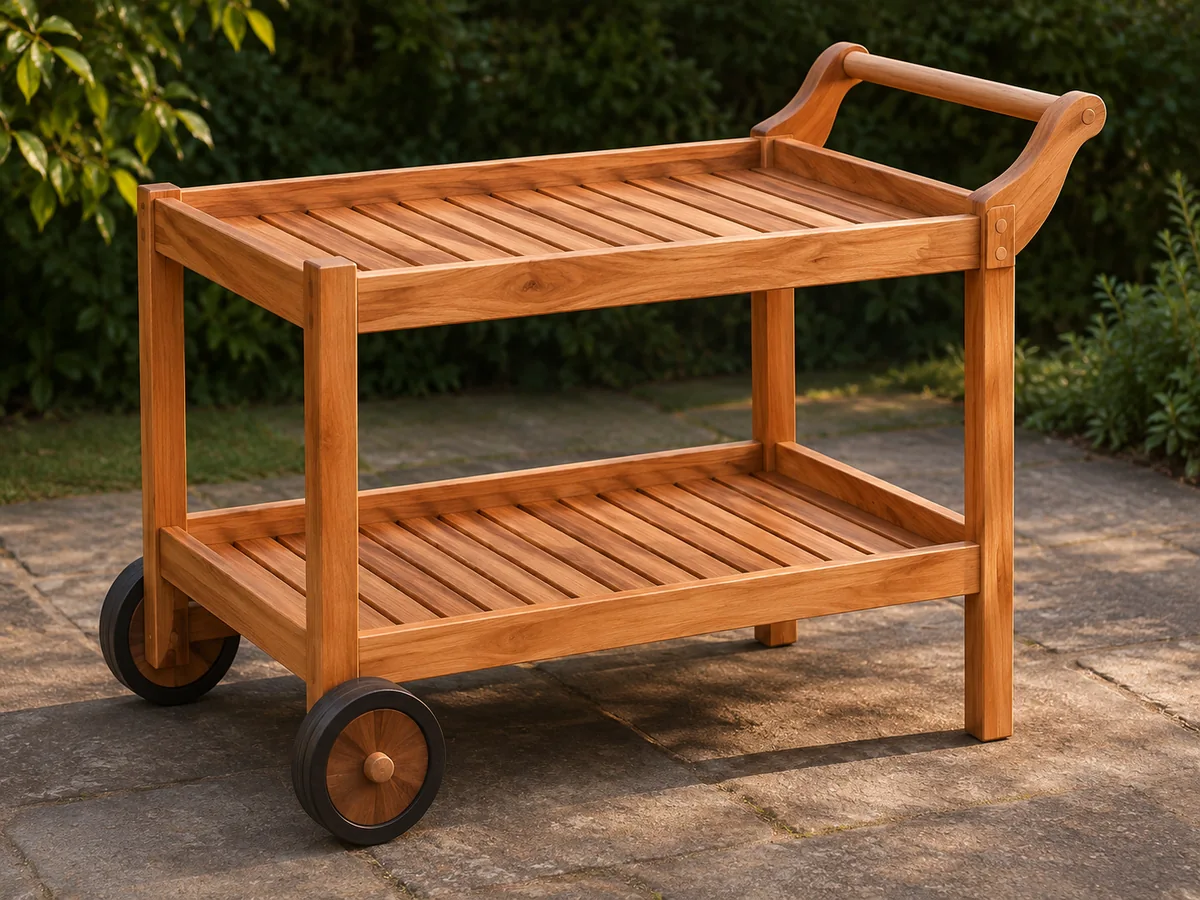
Two equal tray frames are connected by four corner posts.
Project library / Garden & outdoor
Garden & outdoor / Build companion
Two-Tier Garden Trolley
A push trolley carries two slatted trays on a timber frame with two wheels and a dowel handle.
Intermediate6 stages6-page source
A companion to the original plan. An original study guide based on the supplied historical plan; not shop-tested. Use the privately owned source drawings for full-size patterns and complete cutting details.
Understand the project
What makes this build.
The two tray frames are simple, but the wheel axle, unequal leg adjustment and projecting handle must be coordinated before cutting.
One end has wheels and the other fixed feet.
A dowel handle spans shaped projecting brackets.
Points to resolve before building
- The source’s indoor sheet materials are unsuitable for persistent wet exposure.
- Keep hot grills and charcoal off the wooden decks; this is a serving trolley, not a tested grill support.
Prepare the workbench
Materials & tools.
Check what you have, then confirm stock sizes and hardware against your chosen dimensions.
Materials checklist
Tools & operations
- Saw
- Jigsaw
- Drill
- Square
- Clamps
- Sander
Tool choices may include practical editorial suggestions. Use workholding and guarding appropriate to the actual machine and operation.
Choose dry, sound stock and test unfamiliar joints in scrap. Keep guards, push aids, eye protection, and dust control appropriate to the work.
Keep the numbers close
Measurements to know.
Selected dimensions verified from the source. This is not an automatically scaled cutting list.
| Initial leg blanks | Four at 50 × 50 × 750 mm | Source p. 2 |
|---|---|---|
| Handle brackets | Two at 450 mm | Source p. 4 |
| Source wheels | 150 mm diameter | Source p. 2 |
Printed diagrams and concept images are not scale references. Verify measurements, material thickness, hardware fit, and allowances before cutting.
Inches to millimeters
Convert a measurement without changing the design. Enter a decimal or a fraction, such as 1 3/8.
Nominal lumber names and actual finished sizes are different. Converting units does not choose a substitute stock size.
From stock to finished project
Let’s make it.
Read the complete sequence before cutting. Mark a stage complete after its fit checks and any required glue cure.
Resolve the running gear
- Choose the wheels and axle arrangement first. Set the trolley width and wheel-end leg detail around that hardware so the completed trays sit level. Wheel width, hub projection and axle retention can alter the required clearance even when two wheel sets share the same stated diameter.
Before moving onThe axle clearance is included in the drawing.
Make matching tray frames
- Cut the notched rail ends to the actual plan width and assemble two equal rectangles. Check each diagonal before fixing the corners. The source uses rail notches to locate the corners; test these on scrap so both trays finish to the same outside size.
Before moving onBoth trays are square and equal in size.
Fit the slatted decks
- Cut the deck boards to fit their tray frames and fasten them with consistent gaps. If using the sheet-deck alternative, provide the drainage holes described in the source. Keep the board gaps consistent with the expected outdoor moisture movement and avoid pockets where water will collect.
Before moving onNo deck board rocks or projects a sharp edge.
Join trays and legs
- Attach the four posts to both tray frames. Adjust the wheel-end legs to the chosen axle geometry before installing the running gear. Temporarily block the trolley level while marking the axle position so the finished wheel diameter is included in the leg adjustment.
Before moving onThe trolley stands level on its two feet and two wheels.
Fit the push handle
- Shape the paired handle brackets and drill for the dowel crossbar. Fasten the brackets to the upper tray frame and secure the handle against rotation. Check the bracket grain at the handle holes and leave adequate material around them before rounding the bracket outline.
Before moving onThe handle is symmetrical and cannot pull out.
Finish for exposure
- Ease edges and apply a finish suited to the selected timber and outdoor conditions. Recheck wheel retention and tray fasteners after a short unloaded roll. Store the trolley where the selected finish and deck material suit the exposure, and recheck axle retention after its first loaded use.
Before moving onWheels turn freely without rubbing the frame.
1 / 6
Progress and notes stay in this browser. Nothing is uploaded.
Source notes.
- Original PDF
- B-B-Que Trolly.pdf
- Source length
- 6 pages
- Attribution
- Collection copyright 2004 Martian Auctions; original authorship unverified.
- This edition
- 116 Studio · Original written companion and AI concept image · November 2026
Page references count from the first page of this PDF. The original is retained in the owner’s private woodworking collection; it is not distributed by this website. Consult it for full drawings, templates, and details beyond this companion.
Historical plans can omit essential context. Source references identify where a detail came from; they do not certify the design or replace current manufacturer instructions or applicable professional review.
More from this corner of the shop.
Garden & outdoor
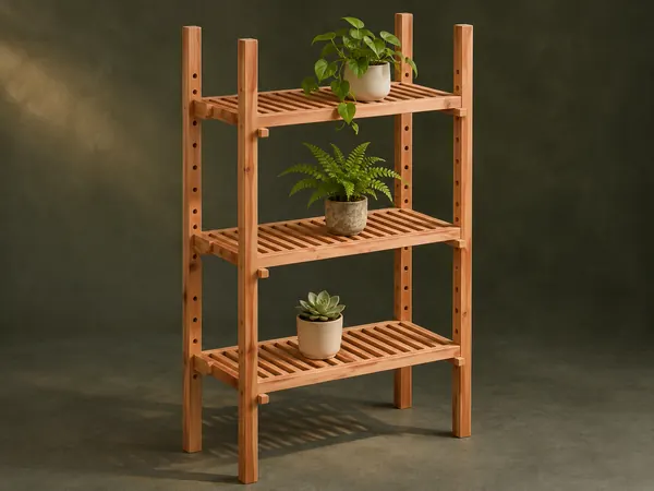
Adjustable Plant Shelves
A tall open plant stand has slatted shelves that slide on four uprights and lock at different heights with wooden pegs.
Intermediate6 stages
 Design study
Garden & outdoor
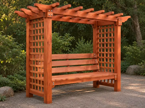
Lattice Arbor Bench
A garden seat sits between lattice side panels beneath an open pergola roof.
Advanced6 stages
Garden & outdoor
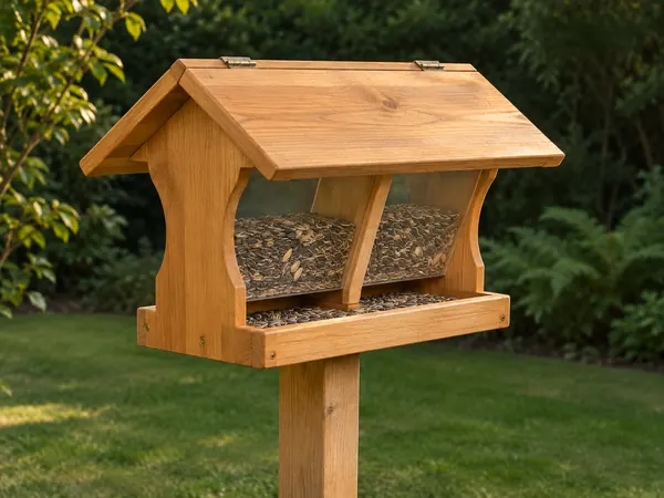
Clear-Sided Seed Feeder
A pitched-roof feeder dispenses seed through a gap below clear sloping hopper panels.
Intermediate5 stages