A turned spindle and close-fitting curved leg joints make this an advanced small table.
Project library / Tables & desks
Tables & desks / Build companion
Concord Candle Stand
A second archival plan for the Concord-style round table, with a turned spindle and three shaped feet.
Advanced5 stages2-page source
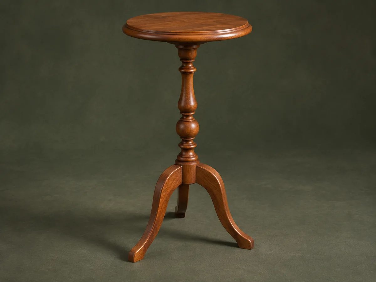
A companion to the original plan. Original guide to an archival plan; not shop-tested. Check the source drawings and actual material sizes before cutting.
Understand the project
What makes this build.
A turned spindle and close-fitting curved leg joints make this an advanced small table.
This is a distinct source edition, not a different invented furniture design.
Points to resolve before building
- Confirm all template dimensions in the original diagram; extracted prose does not constitute a full cutting list.
Prepare the workbench
Materials & tools.
Check what you have, then confirm stock sizes and hardware against your chosen dimensions.
Materials checklist
Tools & operations
- Lathe
- Bandsaw or jigsaw
- Router
- Drill
- Clamps
Tool choices may include practical editorial suggestions. Use workholding and guarding appropriate to the actual machine and operation.
Choose dry, sound stock and test unfamiliar joints in scrap. Keep guards, push aids, eye protection, and dust control appropriate to the work.
Keep the numbers close
Measurements to know.
Selected dimensions verified from the source. This is not an automatically scaled cutting list.
| Top diameter | 16 in | Source p. 2 |
|---|---|---|
| Leg-edge roundover | ¼-in radius | Source p. 2 |
Printed diagrams and concept images are not scale references. Verify measurements, material thickness, hardware fit, and allowances before cutting.
Inches to millimeters
Convert a measurement without changing the design. Enter a decimal or a fraction, such as 1 3/8.
Nominal lumber names and actual finished sizes are different. Converting units does not choose a substitute stock size.
From stock to finished project
Let’s make it.
Read the complete sequence before cutting. Mark a stage complete after its fit checks and any required glue cure.
Trace this edition
- Compare the spindle and leg templates with the brace drawing. Keep this two-page source associated with its own layout even though it depicts the same table family as the longer Concord plan. Check the printed pattern scale against the stated top diameter before treating any traced outline as full size.
Before moving onPatterns and parts all come from this edition.
Turn the central support
- Turn the column to its template and retain the top tenon required by the mounting brace. Sand the turned surfaces while avoiding loose abrasive loops. If the blank is laminated, wait for the adhesive’s specified full cure before mounting it on the lathe.
Before moving onThe brace location and tenon remain intact.
Cut and fit the legs
- Saw three matching legs, round their exposed curves and hollow the contact faces to fit the spindle. Locate the dowel holes with a secure cradle and transfer marks. Leave the straight contact sections unrounded until their concave fit to the spindle has been established.
Before moving onDry-fitted legs meet the spindle cleanly.
Glue the base
- Glue the legs in controlled stages using offcut cauls. Check equal spacing and place the base on a flat surface before the adhesive sets. The bottom of each leg must share the same support plane; correct the dry fit rather than forcing it with clamps.
Before moving onAll feet bear evenly and the spindle is upright.
Complete the round top
- Flatten the glued-up panel, cut the circle and shape the edge. Bore the brace for the spindle tenon, then secure the brace and top with movement-aware fastening. Keep the brace centered and inspect the top edge all the way around for uneven routing or sanding.
Before moving onThe top is level and centered on the tripod.
1 / 5
Progress and notes stay in this browser. Nothing is uploaded.
Source notes.
- Original PDF
- Concorde Table.pdf
- Source length
- 2 pages
- Attribution
- Collection copyright 2004 Martian Auctions; original authorship unverified
- This edition
- 116 Studio · Original written companion and AI concept image · November 2026
Page references count from the first page of this PDF. The original is retained in the owner’s private woodworking collection; it is not distributed by this website. Consult it for full drawings, templates, and details beyond this companion.
Historical plans can omit essential context. Source references identify where a detail came from; they do not certify the design or replace current manufacturer instructions or applicable professional review.
More from this corner of the shop.
Tables & desks
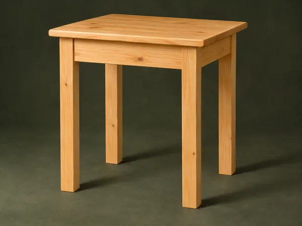
Hand-Tool Side Table
A small pine table uses square legs, mortise-and-tenon aprons and a solid board top.
Intermediate5 stages
Tables & desks
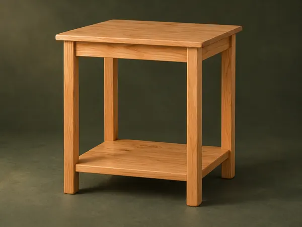
Open-Shelf Bedside Table
A small table has rounded square legs, a solid top and a low shelf captured in leg notches.
Intermediate5 stages
Tables & desks
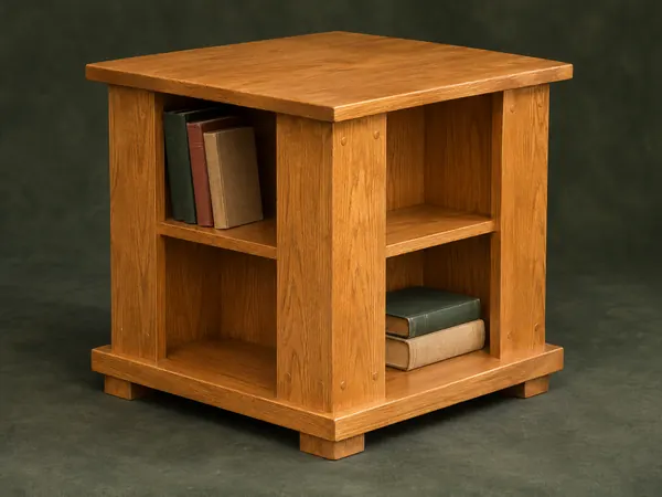
Four-Sided Book Table
A square end table offers small book compartments on four sides beneath a projecting top.
Intermediate5 stages