Several axes allow the head to reach beyond a fixed drill-press table.
Project library / Workshop
Workshop / Design study
Vintage Radial Drill Press
A wall-mounted metal radial drill with a swiveling arm, traversing drill head, and hand-operated feed.
Advanced5 stages4-page source
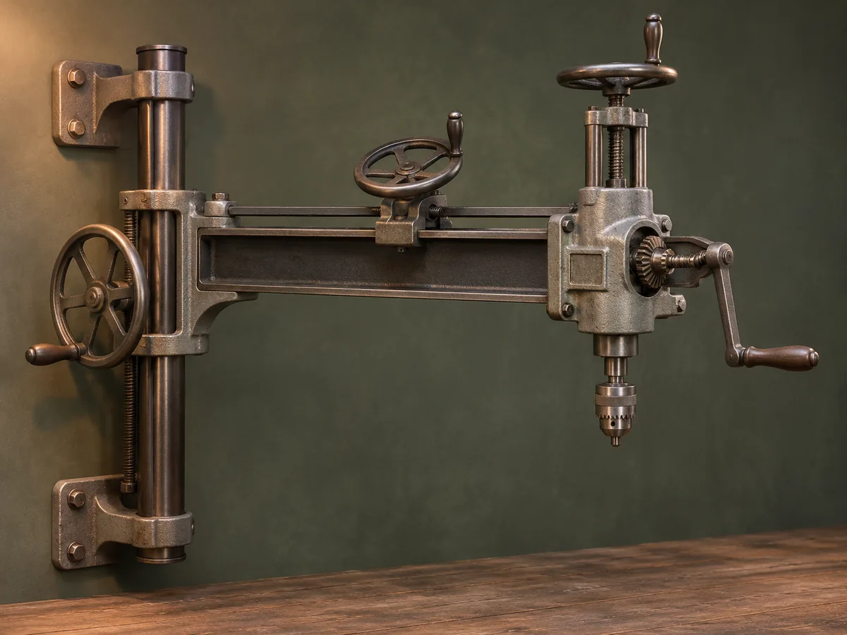
Design review required. Archive study of a machine-tool design. Professional engineering and machining review are required; this walkthrough does not authorize construction or operation. This guide has not been shop-tested.
Understand the project
What makes this build.
Multiple moving machine axes, bearings and load-bearing metal parts require engineering and precision machining.
The source uses hand-operated screws and gears.
Points to resolve before building
- Historical homemade machine, not a certified woodworking appliance.
- A powered conversion needs independent guarding, electrical, structural, and emergency-stop design.
Prepare the workbench
Materials & tools.
Check what you have, then confirm stock sizes and hardware against your chosen dimensions.
Materials checklist
Tools & operations
- Metalworking lathe
- Precision boring and milling equipment
- Measuring and alignment tools
Tool choices may include practical editorial suggestions. Use workholding and guarding appropriate to the actual machine and operation.
Choose dry, sound stock and test unfamiliar joints in scrap. Keep guards, push aids, eye protection, and dust control appropriate to the work.
Keep the numbers close
Measurements to know.
Selected dimensions verified from the source. This is not an automatically scaled cutting list.
| Described reach | 38 in radius from pivot bar | Source p. 2 |
|---|---|---|
| Pivot bar | 2 in cold-rolled steel | Source p. 3 |
| Head slide stock | 36 in length of ½ × 4 in steel | Source p. 2 |
Printed diagrams and concept images are not scale references. Verify measurements, material thickness, hardware fit, and allowances before cutting.
Inches to millimeters
Convert a measurement without changing the design. Enter a decimal or a fraction, such as 1 3/8.
Nominal lumber names and actual finished sizes are different. Converting units does not choose a substitute stock size.
Read, assess & plan
Explore the construction.
Review stages explain the historical design and unresolved decisions; they are not approval to build or use it.
Map the three movements
- Identify arm elevation around the wall pivot, head travel along the arm, and vertical spindle feed. Review the source drawings as a machine-design study before considering fabrication.
Before moving onEach movement has a defined bearing, lock, and travel limit.
Review the support structure
- Assess the channel arm, pivot bearings, wall stringer, and anchorage with a competent machine designer. The old article does not establish a present-day wall load or anchoring specification.
Before moving onA verified support and anchorage design exists.
Plan the slide and saddle
- Study the matched straight slide, filler strip, cast saddle, and adjustable gib. Determine machining accuracy and lubrication provisions before selecting substitute materials.
Before moving onSlide fit and alignment targets are documented.
Review spindle and feed
- Reconcile the bevel gears, tapered spindle bore, feed screw, guide posts, and split feed nut from the detailed drawing. Treat any powered adaptation as a separate guarded machine design.
Before moving onCritical rotating parts and retention details are professionally reviewed.
Define inspection before operation
- Plan alignment, locking, retention, and work-clamping checks before any powered test. Do not infer operating capacity from the historic author’s descriptions.
Before moving onNo operation occurs without a complete commissioning plan.
1 / 5
Progress and notes stay in this browser. Nothing is uploaded.
Source notes.
- Original PDF
- Plans for Radial Drill Press.pdf
- Source length
- 4 pages
- Attribution
- J. V. Romig, “A Radial Drill Press for Small Shop,” Popular Mechanics.
- This edition
- 116 Studio · Original written companion and AI concept image · November 2026
Page references count from the first page of this PDF. The original is retained in the owner’s private woodworking collection; it is not distributed by this website. Consult it for full drawings, templates, and details beyond this companion.
Historical plans can omit essential context. Source references identify where a detail came from; they do not certify the design or replace current manufacturer instructions or applicable professional review.
More from this corner of the shop.
Workshop
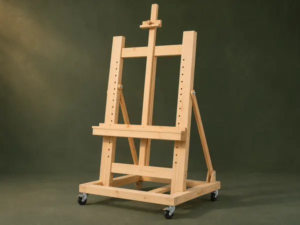
Adjustable Studio Easel
A tall H-frame easel has a pegged canvas shelf, sliding top clamp and hinged rear tilt supports.
Intermediate6 stages
Workshop
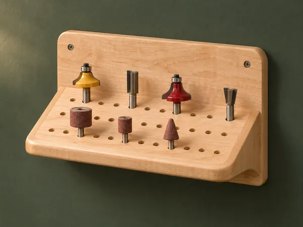
Angled Router-Bit Shelf
A sloping drilled shelf presents router bits and other shanked accessories against a wall backboard.
Beginner5 stages
Workshop
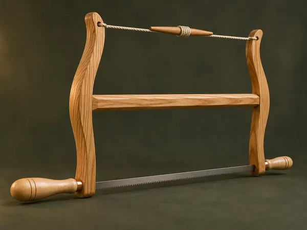
Classic Wooden Bow Saw
An ash H-frame tensions a narrow saw blade with twisted cord and turned maple handles.
Advanced5 stages