Precision setup must be combined with machine-specific protection.
Project library / Workshop
Workshop / Design study
Twin Fence Miter Sled
A plywood table-saw sled with two perpendicular fences for cutting matching frame miters.
Intermediate5 stages2-page source
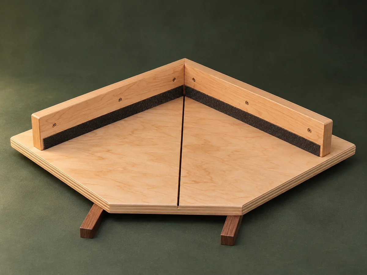
Design review required. Planning overview, not a shop-tested or construction-ready plan. Planning only: the original article lacks complete modern guarding and travel-stop provisions. Do not follow the source suggestion of driving screws through runners and sanding away sharp tips.
Understand the project
What makes this build.
Precision setup must be combined with machine-specific protection.
Two fences form a right angle, so opposite cuts complement each other.
Paired miter runners register the plywood base.
Points to resolve before building
- Planning only: the original article lacks complete modern guarding and travel-stop provisions.
- Do not follow the source suggestion of driving screws through runners and sanding away sharp tips.
Prepare the workbench
Materials & tools.
Check what you have, then confirm stock sizes and hardware against your chosen dimensions.
Materials checklist
Tools & operations
- Saw
- Drill
- Square
- Clamps
Tool choices may include practical editorial suggestions. Use workholding and guarding appropriate to the actual machine and operation.
Choose dry, sound stock and test unfamiliar joints in scrap. Keep guards, push aids, eye protection, and dust control appropriate to the work.
Keep the numbers close
Measurements to know.
Selected dimensions verified from the source. This is not an automatically scaled cutting list.
| Base thickness | ½ inch | Source p. 1 |
|---|---|---|
| Fence relationship | Exactly 90 degrees between the paired fences | Source p. 1 |
Printed diagrams and concept images are not scale references. Verify measurements, material thickness, hardware fit, and allowances before cutting.
Inches to millimeters
Convert a measurement without changing the design. Enter a decimal or a fraction, such as 1 3/8.
Nominal lumber names and actual finished sizes are different. Converting units does not choose a substitute stock size.
Read, assess & plan
Explore the construction.
Review stages explain the historical design and unresolved decisions; they are not approval to build or use it.
Review saw compatibility
- Measure the miter slots, blade travel and available guarding. Design the sled travel stops, hand-clearance zones and blade-exit protection before making the jig.
Before moving onThe jig has a safe reviewed operating envelope.
Fit the runners
- Fit the two guides to slide without side play or binding. Attach them to the flat base with screws sized to avoid exposed tips.
Before moving onThe base moves smoothly while remaining registered.
Establish the fence geometry
- Mark the saw kerf reference with an approved setup, then position the paired fences at a true right angle. Keep fasteners out of the blade path.
Before moving onBoth fences are secure and clear of the blade travel.
Calibrate with test pieces
- Use adequately supported scrap to make a four-corner test frame. Adjust the fences until all corners close without cumulative angular error.
Before moving onThe test frame closes evenly at all four corners.
Complete the safety details
- Fit the planned stops, hold-down arrangements and blade-exit protection, then apply the abrasive fence facing. Review the completed unpowered jig before use.
Before moving onHands remain outside the blade path and the sled cannot overtravel.
1 / 5
Progress and notes stay in this browser. Nothing is uploaded.
Source notes.
- Original PDF
- Table Saw Mitre Jig.pdf
- Source length
- 2 pages
- Attribution
- WOOD magazine, Tablesaw Miter Jig, © Meredith Corporation 2004.
- This edition
- 116 Studio · Original written companion and AI concept image · November 2026
Page references count from the first page of this PDF. The original is retained in the owner’s private woodworking collection; it is not distributed by this website. Consult it for full drawings, templates, and details beyond this companion.
Historical plans can omit essential context. Source references identify where a detail came from; they do not certify the design or replace current manufacturer instructions or applicable professional review.
More from this corner of the shop.
Workshop
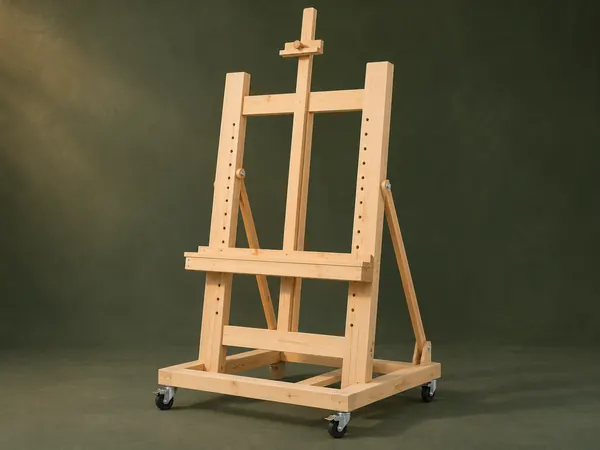
Adjustable Studio Easel
A tall H-frame easel has a pegged canvas shelf, sliding top clamp and hinged rear tilt supports.
Intermediate6 stages
Workshop
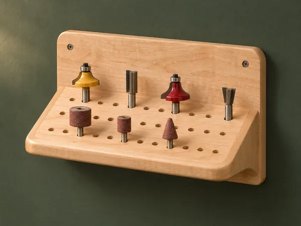
Angled Router-Bit Shelf
A sloping drilled shelf presents router bits and other shanked accessories against a wall backboard.
Beginner5 stages
Workshop
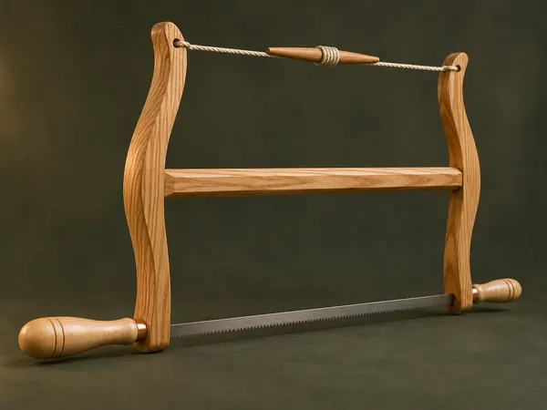
Classic Wooden Bow Saw
An ash H-frame tensions a narrow saw blade with twisted cord and turned maple handles.
Advanced5 stages