Large laminations and built-in joinery demand accurate sequencing and substantial clamping.
Project library / Workshop
Workshop / Build companion
Laminated Knockdown Workbench
A heavy workbench made from thin-board laminations, with wedged stretchers, two lower shelves and a segmented slab top.
Advanced7 stages14-page source
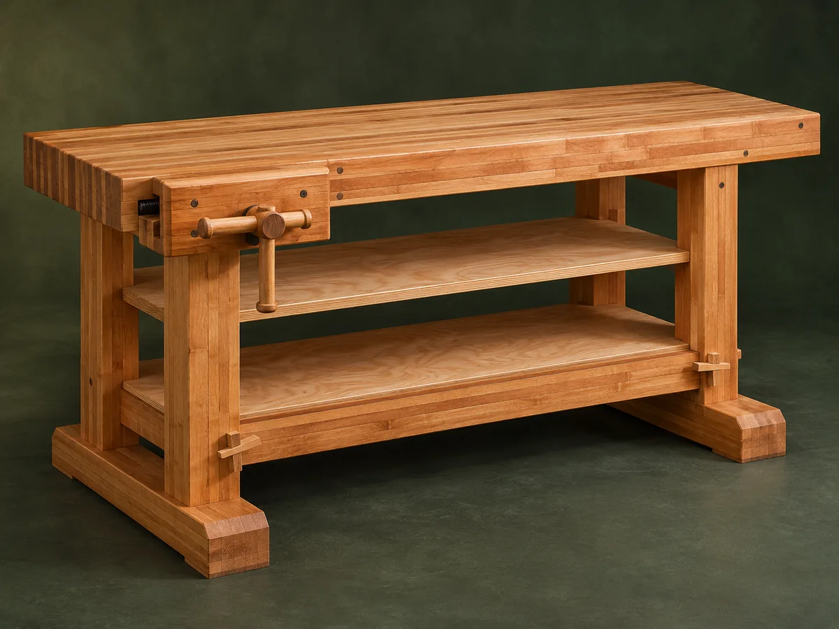
A companion to the original plan. Original reading guide based on the archived plan; not shop-tested. Confirm diagram dimensions against the private source before cutting.
Understand the project
What makes this build.
Large laminations and built-in joinery demand accurate sequencing and substantial clamping.
Wedged lower stretchers allow knockdown assembly.
Three top sections are drawn together with threaded rods.
Points to resolve before building
- Do not adopt the source’s permissive advice about weak or badly defective boards.
- Threaded rods need inspection as wood moves; tightening must not crush the top.
- Vise installation is not fully covered in this capture.
Prepare the workbench
Materials & tools.
Check what you have, then confirm stock sizes and hardware against your chosen dimensions.
Materials checklist
Tools & operations
- Saw
- Drill
- Clamps
- Router flattening sled
- Plane
- Chisels
Tool choices may include practical editorial suggestions. Use workholding and guarding appropriate to the actual machine and operation.
Choose dry, sound stock and test unfamiliar joints in scrap. Keep guards, push aids, eye protection, and dust control appropriate to the work.
Keep the numbers close
Measurements to know.
Selected dimensions verified from the source. This is not an automatically scaled cutting list.
| Top lamination blanks | Forty-eight pieces, 1½ × 84 inches, thickness from actual stock | Source p. 2 |
|---|---|---|
| Main stretcher blanks | 3 × 60 inches in source list | Source p. 2 |
Printed diagrams and concept images are not scale references. Verify measurements, material thickness, hardware fit, and allowances before cutting.
Inches to millimeters
Convert a measurement without changing the design. Enter a decimal or a fraction, such as 1 3/8.
Nominal lumber names and actual finished sizes are different. Converting units does not choose a substitute stock size.
From stock to finished project
Let’s make it.
Read the complete sequence before cutting. Mark a stage complete after its fit checks and any required glue cure.
Plan the lamination map
- Label every layer of each post, rail and stretcher, identifying where gaps form mortises or extensions form tenons. Use sound wood around all joints rather than burying structural defects. Keep structural defects away from tenons, mortise walls and wedge openings, even when the surrounding timber contains several laminated layers.
Before moving onEvery layer has a defined orientation and joint function.
Prepare and align stock
- Straighten reference edges and cut repeatable widths and lengths. Drill matching dowel-alignment holes so glue pressure cannot shift the built-in joints. Use two locating dowels per layer where the design requires alignment; a single dowel can still allow a part to rotate.
Before moving onA dry stack produces accurate shoulders and mortises.
Glue the structural members
- Laminate manageable groups on a flat surface, keeping adhesive out of the intended mortises. Clean and flatten the cured members before fitting the stretcher joints. Apply adhesive according to its current spread and open-time instructions, dividing the work into batches that can be clamped before it skins.
Before moving onLaminations are sound and joint surfaces remain usable.
Assemble the knockdown base
- Fit the posts into rails and the long stretchers through the post mortises. Add the wedges, shelf supports and notched plywood shelves, checking square and racking resistance. Fit the shelf rails before closing the end frames, since these smaller captive members cannot easily be inserted afterward.
Before moving onBase is rigid and can be dismantled as intended.
Laminate the top sections
- Make the separate top slabs with aligned threaded-rod holes. Check twist with winding sticks during glue-up, then flatten each section on a securely supported setup. The router-flattening rails must be coplanar and securely fixed; a smooth router pass will reproduce any error in their setup.
Before moving onThe slabs are flat and their joining holes align.
Join and attach the top
- Use the locating dowels and threaded rods to bring the slabs together. Fit front fasteners and rear sliding keeper cleats to permit movement, then flatten the assembled working surface. Recheck threaded-rod tension over seasonal changes without overtightening, and keep access to the recessed nuts for later adjustment.
Before moving onTop is secure, coplanar and allowed to move seasonally.
Plan workholding hardware
- The photo shows vises, but the captured article does not provide their complete installation. Choose compatible hardware and lay it out clear of rods, cleats and dog locations before adding it. Lay out vise screws and dog holes on both faces of the top so they cannot strike a concealed threaded rod or mounting bolt.
Before moving onEvery workholding addition has its own verified installation detail.
1 / 7
Progress and notes stay in this browser. Nothing is uploaded.
Source notes.
- Original PDF
- Traditional Workbench 1.pdf
- Source length
- 14 pages
- Attribution
- Jeff Greef Woodworking, Traditional Workbench, archived 2003.
- This edition
- 116 Studio · Original written companion and AI concept image · November 2026
Page references count from the first page of this PDF. The original is retained in the owner’s private woodworking collection; it is not distributed by this website. Consult it for full drawings, templates, and details beyond this companion.
Historical plans can omit essential context. Source references identify where a detail came from; they do not certify the design or replace current manufacturer instructions or applicable professional review.
More from this corner of the shop.
Workshop
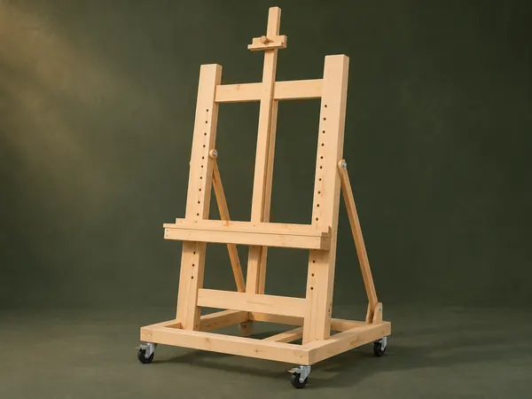
Adjustable Studio Easel
A tall H-frame easel has a pegged canvas shelf, sliding top clamp and hinged rear tilt supports.
Intermediate6 stages
Workshop
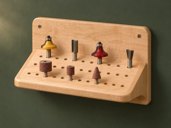
Angled Router-Bit Shelf
A sloping drilled shelf presents router bits and other shanked accessories against a wall backboard.
Beginner5 stages
Workshop
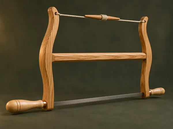
Classic Wooden Bow Saw
An ash H-frame tensions a narrow saw blade with twisted cord and turned maple handles.
Advanced5 stages