Large dovetails, moving vise joinery and thick-stock milling make this an advanced bench build.
Project library / Workshop
Workshop / Build companion
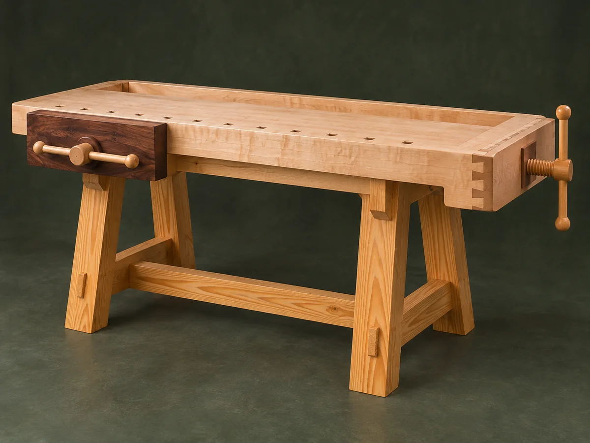
Maple Tail Vise Workbench
A traditional maple workbench with a rear tool well, square bench-dog row, front vise and wooden tail vise on a pine trestle base.
Advanced8 stages60-page source
A companion to the original plan. Original reading guide based on the archived plan; not shop-tested. Confirm diagram dimensions against the private source before cutting.
Understand the project
What makes this build.
Large dovetails, moving vise joinery and thick-stock milling make this an advanced bench build.
A maple top and contrasting walnut vise faces sit above a pine base.
The rear tool well includes ramps for brushing out shavings.
The author’s narrative records changes from the preliminary materials list.
Points to resolve before building
- The source is a documented personal build, not a shop-tested universal hardware specification.
- Do not reproduce nail-bearing planer sleds or continue forcing an overloaded saw that trips breakers.
- The very heavy top needs planned support and assistance during handling.
Prepare the workbench
Materials & tools.
Check what you have, then confirm stock sizes and hardware against your chosen dimensions.
Materials checklist
Tools & operations
- Saw
- Bandsaw
- Router with templates
- Drill or drill press
- Planes
- Chisels
- Heavy clamps
Tool choices may include practical editorial suggestions. Use workholding and guarding appropriate to the actual machine and operation.
Choose dry, sound stock and test unfamiliar joints in scrap. Keep guards, push aids, eye protection, and dust control appropriate to the work.
Keep the numbers close
Measurements to know.
Selected dimensions verified from the source. This is not an automatically scaled cutting list.
| Main top slab | 2½ inches thick × 17 inches wide in documented build | Source p. 11 |
|---|---|---|
| Design length | About 6 feet, chosen for the author’s shop | Source p. 4 |
| Base feet | 2¾ × 4 × 27 inches in source list | Source p. 7 |
Printed diagrams and concept images are not scale references. Verify measurements, material thickness, hardware fit, and allowances before cutting.
Inches to millimeters
Convert a measurement without changing the design. Enter a decimal or a fraction, such as 1 3/8.
Nominal lumber names and actual finished sizes are different. Converting units does not choose a substitute stock size.
From stock to finished project
Let’s make it.
Read the complete sequence before cutting. Mark a stage complete after its fit checks and any required glue cure.
Choose hardware before milling
- Obtain the actual front-vise and tail-screw hardware and map their travel, dog-hole locations and underside supports. Treat the source’s preliminary cut list as a starting point and reconcile it with the later fitted dimensions. The author specifically encountered a dog hole beneath a guide block; avoid repeating that conflict by drawing the underside hardware first.
Before moving onHardware, top geometry and dog positions agree.
Mill and glue the top slab
- Acclimate sound maple, establish flat reference faces and glue the slab with aligned edges. Use machinery within its capacity and safe supported workholding for the heavy parts. Allow rough-milled thick stock to settle before final sizing and use winding sticks to verify that the reference face remains untwisted.
Before moving onThe cured slab is square-ended and ready for the front strip.
Make the dog strip and end caps
Source pp. 12, 16, 17, 18, 19, 20, 22, 23, 24
- Template the angled square dog pockets clear of vise hardware, then fit the strip and large end dovetail. Fit end-cap splines and bolts while preserving cross-grain movement. Keep the end-cap spline free to slide where the grain crosses the top, and limit glue to the intended fixed front area.
Before moving onDogs move freely and end caps do not restrain the whole top width.
Build the rear tool well
- Fit the dovetailed rear apron, bottom and cleanout ramps. Use appropriate slotted attachments for a solid-wood bottom and keep underside spacers clear of both vises. The cleanout ramps should meet the tray bottom smoothly so shavings can be brushed out rather than caught behind a raised lip.
Before moving onThe well is accessible and movement details remain free.
Fit the front vise
Source pp. 29, 30, 31, 32, 33, 34
- Shape the maple-and-walnut jaw and transfer the actual hardware hole positions. Plane the clamping faces true before fastening the carriage, then test full travel. Transfer hole centers from the actual carriage instead of relying on the author’s rod diameters, which belong to his selected hardware.
Before moving onJaw closes evenly and rods do not bind.
Construct the tail vise
Source pp. 35, 36, 37, 38, 39, 40, 41, 42, 43, 44, 45, 47, 48, 49
- Dry-fit the dovetailed jaws, face piece and runner system, then locate guide blocks from the assembled mechanism. Keep guide blocks removable for adjustment and fit cap dog holes to their actual positions. Move the dry-fitted tail vise through its full range before fixing each guide block, checking both jaw alignment and dog-hole clearance.
Before moving onThe vise travels squarely without rubbing or racking.
Build and fit the trestle base
- Join the feet, uprights and stretchers with fitted mortise-and-tenon joints. Keep the base square and level it at the floor rather than deliberately building twist into it; fit the top locating dowels. The locating dowels should enter without forcing the heavy top sideways; verify their center positions with a dry transfer layout.
Before moving onThe bench stands securely and the top registers on its supports.
Flatten and commission
Source pp. 55, 56, 57, 58, 59, 60
- With the top supported, check it with winding sticks and a straightedge, then plane high spots carefully. Apply a suitable bench finish and retest both vises and every dog position after curing. Check the vise cap against the main top during final flattening so a workpiece bridges them without catching at the moving joint.
Before moving onThe surface is flat and workholding operates smoothly.
1 / 8
Progress and notes stay in this browser. Nothing is uploaded.
Source notes.
- Original PDF
- Traditional Workbench 2.pdf
- Source length
- 60 pages
- Attribution
- Keith S. Rucker, Building a Traditional Workbench, © 2000.
- This edition
- 116 Studio · Original written companion and AI concept image · November 2026
Page references count from the first page of this PDF. The original is retained in the owner’s private woodworking collection; it is not distributed by this website. Consult it for full drawings, templates, and details beyond this companion.
Historical plans can omit essential context. Source references identify where a detail came from; they do not certify the design or replace current manufacturer instructions or applicable professional review.
More from this corner of the shop.
Workshop
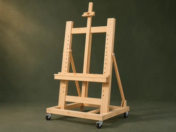
Adjustable Studio Easel
A tall H-frame easel has a pegged canvas shelf, sliding top clamp and hinged rear tilt supports.
Intermediate6 stages
Workshop
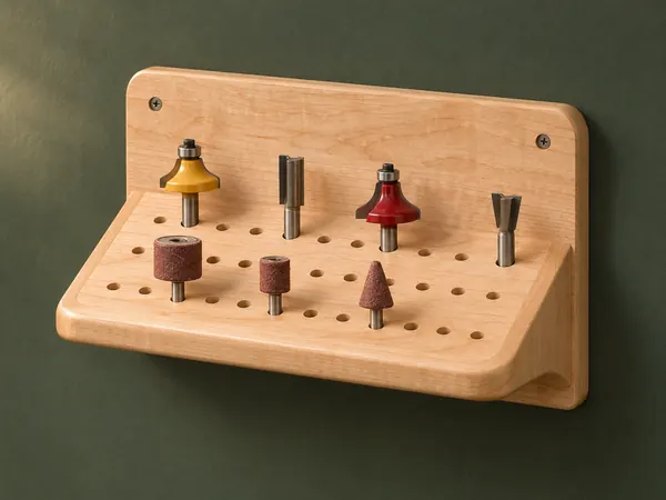
Angled Router-Bit Shelf
A sloping drilled shelf presents router bits and other shanked accessories against a wall backboard.
Beginner5 stages
Workshop
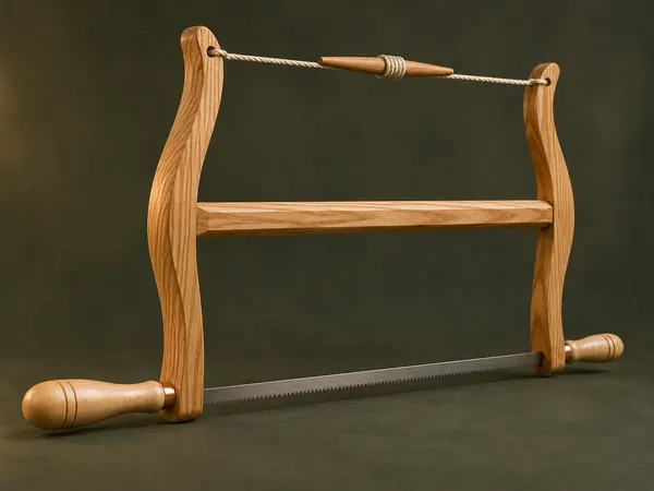
Classic Wooden Bow Saw
An ash H-frame tensions a narrow saw blade with twisted cord and turned maple handles.
Advanced5 stages